How to Properly Install BMT and VDI Driven Tool Holders: Zero-point Position Alignment, Noise Inspection, and Installation Precautions
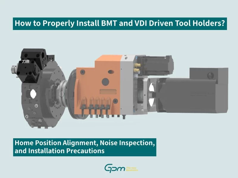
How to Properly Install BMT and VDI Driven Tool Holders: Zero-point Position Alignment, Noise Inspection, and Installation Precautions
Although installing a driven tool holder may appear easy and simple, it involves proper alignment of the transmission mechanism, zero-point position, coupling position, and positioning procedures. Failure to complete these steps correctly may result in inaccurate positioning, tool holder jamming, or even damage to the driven tool holder and gearbox components.
What Should Be Checked When There Is Abnormal Noise in Driven Tool Holder?
If abnormal noise occurs during operation, highly recommend removing all driven tool holders first to identify the source of the noise. The following points should be checked:
- Whether the noise originates from the transmission mechanism itself.
- Whether the coupling center position of the drive mechanism has shifted from the tool disc.
- Whether driven tool holder components have worn due to long-term use.
Why Is It Necessary to Confirm the Zero-point Before Installation?
Before installation, the transmission mechanism must be at the correct zero-point position.
BMT and VDI tool holders use different coupling and positioning methods; positioning must be performed according to the corresponding tool holder type.
BMT-DIN1809 Driven Tool Holder Installation Precautions
For BMT-DIN1809 transmission system, the coupling teeth of the gearhead must be at zero-point position before tool changing or turret rotation. If the coupling teeth are not at the zero-point position, do not change tools or rotate the turret.
When installing a BMT driven tool holder, do not simply tighten and secure the tool holder. First, confirm the gearhead zero-point position, coupling position, and alignment with the turret disc hole.
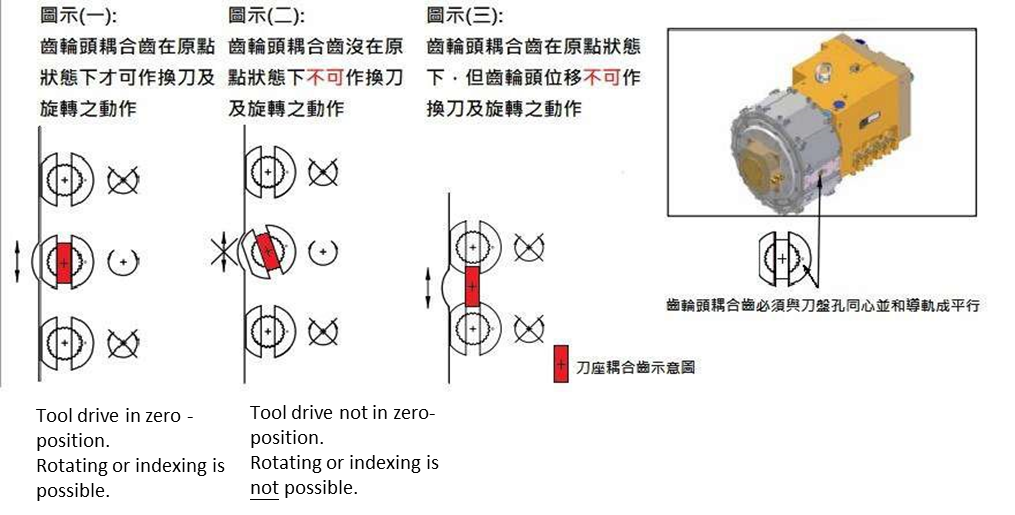
Figure 1. BMT-DIN1809 Transmission System and Tool Holder Coupling Diagram
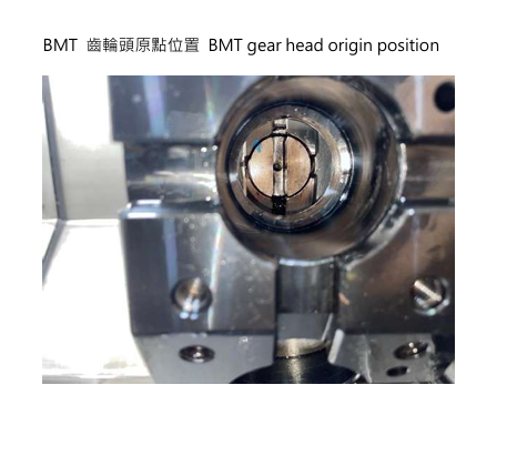
Figure 2. BMT Gearhead Zero-point Position Diagram
Why VDI-DIN5480 Driven Tool Holder Require Manual Positioning?
Before installing a VDI-DIN5480 driven tool holder, manual positioning must be performed. Both the axial gearbox and radial gearhead is located at the 3 o’clock position.
Before mounting the VDI driven tool holder onto the tool disc, manually rotate the coupling section and confirm the coupling locating pin is fully engaged in the locating slot.
Failure to perform manual positioning before installation may result in:
- Inaccurate driven tool holder positioning
- Tool holder jamming
- Damage to driven tool holder components
- Damage to gearbox drive mechanism components
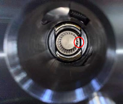
Figure 3. VDI-DIN5480 Transmission System and Tool Holder Coupling Diagram
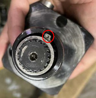
Figure 4. Axial Gearbox and Radial Gearhead 3 O’clock Zero-point Position
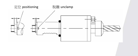
Figure 5. VDI Locating Pin and Locating Slot Position Diagram
BMT and VDI Driven Tool Holder Pre-Installation Checklist
Before installation, verify the following items:
- Confirm the transmission mechanism is at the zero-point position.
- Do not install the driven tool holder directly from the working position.
- Check for coupling center deviation.
- Inspect tool holder components if wear-out.
- For BMT, confirm that the gearhead coupling teeth are at the zero-point position.
- For VDI, complete manual positioning before installation.
- For VDI, verify that the locating pin is properly engaged in the locating slot.
- If abnormal noise occurs, remove the tool holder and identify the source before proceeding.
Conclusion
BMT and VDI driven tool holders have different coupling and positioning requirements. Verifying the drive mechanism zero-point position, coupling alignment, and component condition before installation is essential to prevent inaccurate positioning, tool holder jamming, and component damage.
Frequently Asked Questions (FAQ)
Can a BMT Driven Tool Holder Perform a Tool Change If It Is Not at the Zero-point Position?
No. For BMT-DIN1809 systems, the gearhead coupling teeth must be positioned at the zero-point position before tool change and rotation can be performed.
Can a VDI Driven Tool Holder Be Installed Directly?
No. VDI-DIN5480 driven tool holder must be manually positioned before installation, and the coupling locating pin must be confirmed to be fully engaged in the locating slot.
What Should Be Done If There Is Abnormal Noise in Driven Tool Holder?
Remove the driven tool holder and determine whether the noise originates from the transmission mechanism itself, coupling offset, or worn out components.
Further Reading
If the equipment already exhibits abnormal noise, insufficient power, positioning abnormalities, or driven tool holder failure, please refer to the troubleshooting guide below or contact the GPM team.
Updated: 2026/11/05