What to Do When Turret Fails to Operate?
Turret is one of the key components in CNC machines. When the turret fails to operate, it not only affects production, but may also lead to severe equipment damage. Therefore, it’s crucial to take immediate inspection and corrective measures when issues arise with the turret.
This article provides a detailed inspection SOP when the turret is not functional and helps machine operators quickly identify problems and do trouble shooting.
Part One: Check if there is any alarm code on the Delta Drive unit?
1.1 What are Alarm Codes?
When the turret is mal-functioned, errors will be displayed by alarm codes (ALXXX) on the operation panel or control system. These alarm codes are alerts triggered by the turret internal diagnostics to indicate abnormal conditions, providing critical clues for diagnosing the issue.
(For Delta drive unit alarm codes, refer to the following links)
Delta A2 Drive unit Alarm Codes, Delta B3 Drive unit Alarm Codes
1.2 Steps to check the alarm codes of the Turret Drive unit
- Check the Operation Panel: When the turret fails to operate, first check the operation panel or controller screen for any displayed alarm codes. If alarm codes appear, record the alarm codes.
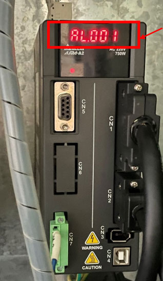
- Check the meanings of the Alarm Code: Refer to the operational manual, technical documents, or website database to find detailed explanations for the corresponding alarm codes. Usually, these codes provide specific descriptions regarding drive unit faults, overloads, abnormal voltage, or other potential issues.
(For Delta drive unit alarm codes, refer to the following links)
Delta A2 Drive unit Alarm Codes, Delta B3 Drive unit Alarm Codes
Part Two: Check if the marking line on the Tool Disc is Aligned?
1. Purpose of the marking line
If the marking line on the tool dis is not aligned, it will cause unable to mount tool holders correctly and properly, thus affecting production accuracy and quality. Therefore, it is essential to regularly check the alignment of the marking line.
2. Steps to Check the marking line
2.1 Stop Machine for Inspection: Turn off the machine and stop the turret in a safe position. It is prohibited to operate the machine during inspections to avoid any injuries.
2.2 Observe the marking line: Use a lighting tool to examine the marking line on the tool disc to confirm it is perfectly aligned with the corresponding mark on the turret base. Even minor deviations should be corrected immediately (see step 2.3).
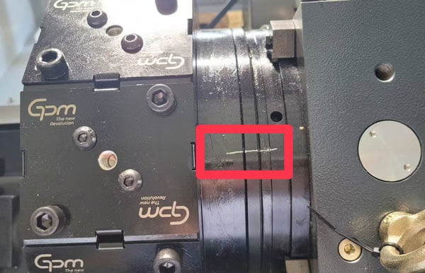
2.3 Adjust the Tool Disc: If there is a deviation in the marking line, re-adjust the tool disc manually or through the control system to align with the mark on the turret base.
2.4 Test after alignment: After adjustment, conduct an indexing test to see if the tool disc may rotate to the designated position smoothly. If indexing does not function correctly, please immediately contact GPM for assistance.
3.FAQ
3.1 Excessive Deviation of the marking line
If the marking line is excessively misaligned and cannot be manually adjusted or automatically calibrated through the control system, it indicates possible damage or wear in turret. Please immediately contact GPM for assistance.
3.2 Repeating Misalignment of the marking line
If turret frequently has misalignment of the marking line, it could be due to loosen mechanical connections, sensor failure, or turret aging. Stop the machine to have a thorough inspection or contact GPM for assistance.
3.3 Confirm Hydraulic Pressure is within Required Values
Adjust the hydraulic system pressure to a stable value of 50 bar ±10. Insufficient hydraulic pressure can lead to tool change errors and inadequate clamping force during machining.
Conclusion
If the problems remain after following the above steps, please contact GPM for troubleshooting.
Updated: 2025/09/01